Blackmagic Design make some really awesome hardware. With some shitty flaws that means they break on lousy parts like a micro USB-connector.
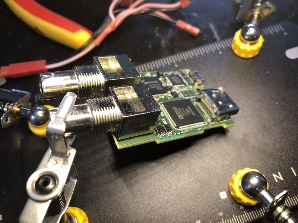
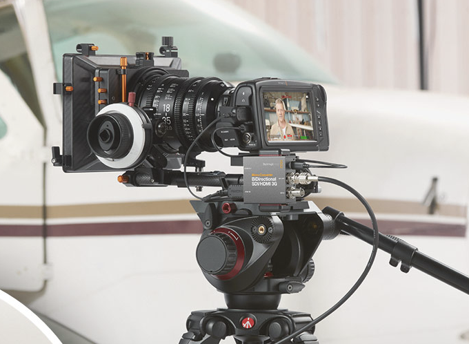
I recently got a SDI-HDMI converter that only powered on intermittedly, probably because of the micro-USB connector coming loose after a mechanical shock/snag/… accident.
The current version of these is using USB-C, which is a lot more mechanically robust. But still, if you’re using these in a production environment, you’ll probably want to tape down the wires so there is no accidental force on the connector. It’s not really a field-proof power supply connector imho, especially for the types of environment BMD’s customers operate in.
To be fair, there is a plastic block holding the USB-connector down, but mechanically that doesn’t do much. A proper design of the connector’s PCB footprint might have saved this specimen though.
Fault finding 1
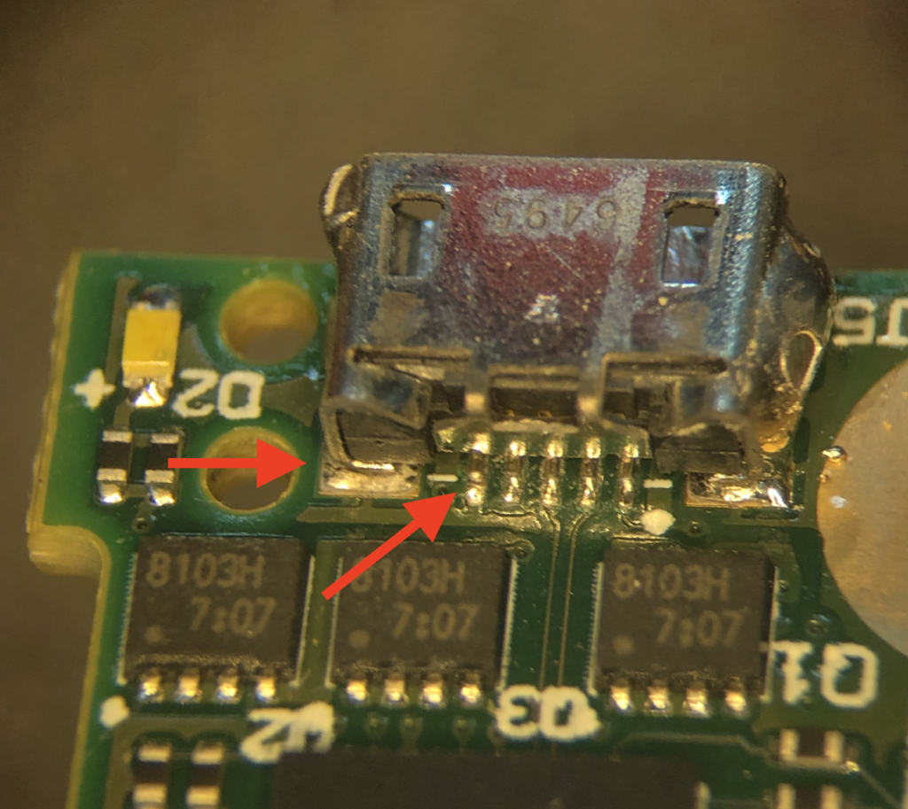
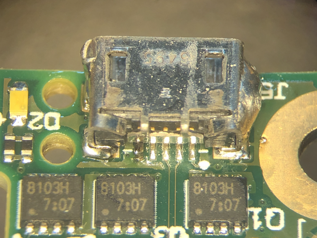
Under a microscope, cracks in the soldering of the connector are clearly visible. There’s a nice power LED (D2) next to the connector. Let’s get those cracks fixed up and power it up.
Fault finding 2
Insert power – “pop”! But no light. Hmmm. Maybe the seller lied about it working intermittently? Was it maybe fried altogether? Check all IC’s for visual damage or magic smoke – nothing. No smell either.
Turned out that the “pop”-sound was made by something else completely unrelated. Look closely at the rightmost pin on the connector (next to the white dot – VCC or +5v). Looks good, right?
The real culprit
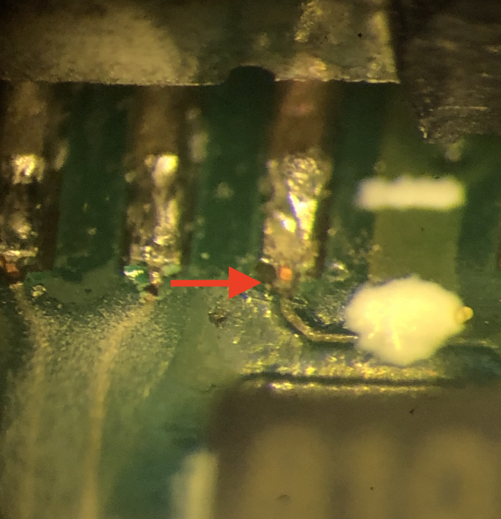
Turns out that the power for this thing runs through a *tiny* (4mil?) trace which also had been severed clean when the force was applied. Very hard to spot, even under a professional stereo microscope with proper lighting (and experience).
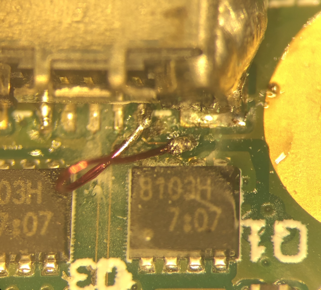
Fix
Mitigation
If you use BMD products (or any devices with micro USB or similarly flimsy connectors) in a rough environment, secure down the cable (e.g. with gaffer tape) near the connector. This way, pulling the cable doesn’t disconnect or break the connector.
One more step could be to put blocks of wood, LEGO or similar material around the connector to create a ‘hole’ for the connector to live in, so any snagging, pulling or falls strains the block in stead of the connector.dwdew
Proper mitigation
If you’re a device designer, PCB layouter, product architect or in any similar position to do something about this during design or scoping of the project – do so. Millions of devices end up in landfill because of simple problems like this – while the world is quite literally on fire.
I’ve fixed tens (maybe a hundred?) devices with this problem. Usually, the time-cost doesn’t match the value of the item (hello Chinese disco-light!). BMD is by no means the only company not doing this right.
Some Tips:
- Select the most robust connector (type) that’s available and appropriate for the job (I can understand going for micro-USB here because of the versatility, cost, and ubiquitous-ness back when it was designed (2015).
- Design the enclosure such that the connector receptacle is as recessed as possible. This way, the bulky, ‘hard’ part of the connector plug sticks out as little as possible, lowering the chance of impacts and shortening the ‘arm’ of a moment that is applied to the receptacle in case of a snagging momentum on the cable.
- Mount the receptacle as sturdy as possible within the constraints of your assembly (soldering) workflow. No tiny traces. No relying (solely) on copper-substrate bonding. Use the board’s thickness and the mechanical resilience of vias to your advantage.
USB-C receptacles are much better in this respect because of their pins that actually pierce the board in stead of just sitting on top (and relying on the copper bonding). - Add extra mechanical anchoring: Add clear copper pads next to a connector to (manually) add bulk solder blobs if necessary. Anchor the receptacle to the enclosure if possible. Add mechanical brackets over a connector (that actually do something – see next point). Hell, break out the hotmelt gun if you’re skimping.
- Test! TEST! Test the living bejesus out of your prototypes and products. Put yourself in the boots of your users. If it’s meant to be used on a film set, visit those. Products will fall. Cables will be pulled by a stray piece of equipment.
Put a weight on a typical cable and let it swing while plugged into your device. Let if fall. If the connection breaks, the cable (plug) should break – (and this is important) the receptacle should be fine. Cables are almost free – the device is expensive.
Keep in mind: Circuit board, thin copper traces and solder are all very brittle – meaning there is little displacement required for the mechanical and electrical connections to get separated. Even a tiny tolerance or play (e.g. on a bracket) of say 0,2mm might be enough to reach ‘yield’ conditions in any of those. Make sure they can’t be reached (with a safety margin). That’s why the plastic block holding down the USB-connector inside this product is a non-working afterthought.
But!…
Yes this adds costs. But these are tiny in comparison to the cost of products failing, (film) productions halted or delayed, and the damage to your brand’s reputation. The environment (and your users, co-workers in warranty, stock holders etc. etc.) will thank you.
Like this? You might be interested in my latest project. It's a desk light made completely from a single sheet of printed circuit board. Check it out: